When two or more devices are connected together through physical/logical connection for resource sharing or services, that forms a network
- LAN enables devices within small geographical area to connect and communicate with each other.
- WAN enables a large geographical area connect each other, often covering multiple LAN's.
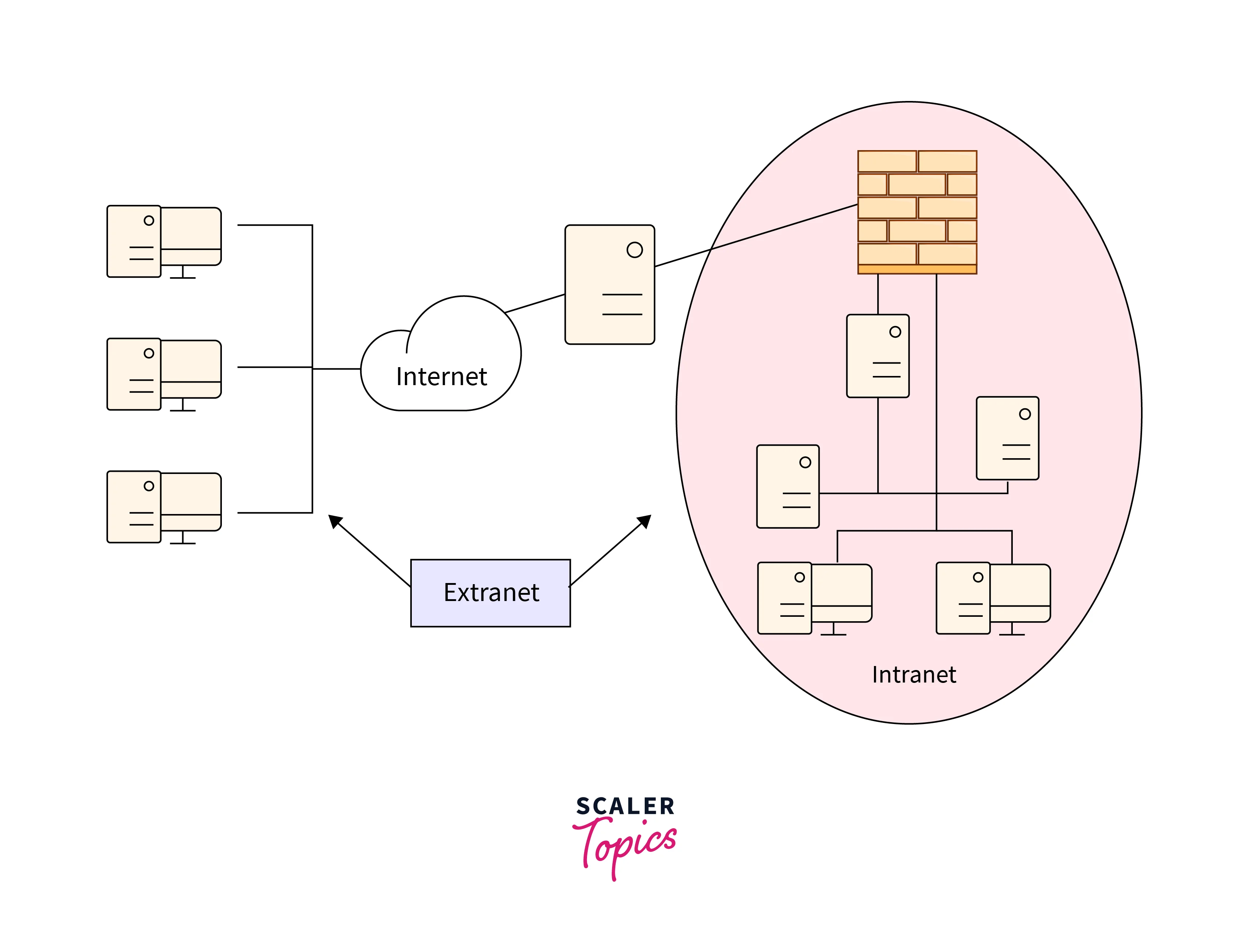
- Internet is a global network that connect billions of devices together through WAN.
- Intranet is a private network that exist in the internet, typically uses LAN infrastructure to create a controlled and secure environment for services and resource sharing.
- Extranet is an extension of intranet network for authorized external users through public telecommunication systems. It securely connects different networks or parts of networks to share information or service.
Internetworking is a technique of connecting different networks or network segments by using network devices such as router, switches, access points and more.

Hub is a basic networking device that operates at physical layer (1) of OSI model. It simply connects multiple devices, when a device sends data through hub, it broadcasts that data to all the connected devices. This inefficeincy results in network congestion (taking up bandwidth). As hub runs in half duplex transmission mode, only one device can communicate at a time, There is no simultaneous transmission and receiving while using a hub. Since all traffic are shared, an attacker can eavesdrop on the communication through a compromised device or through physical port connection. Through further escalations, the attacker can ARP poison the network for MAC and IP for spoofing and MTM, this is an inherent security risk.
Speed- 10Mbps, Ports- 4/12, Transmission type- Frame flodding unicast, broadcast or multicast
unicast-one to one, multicast- one to many or many to many, broadcast- one to all communication

Switch is an advanced networking device that operates at Data Link layer (2) of the OSI model. It is responsible for receiving, processing, and forwarding network traffic based on destination MAC addresses. They provide both half & full duplex transmisssion mode, increasing network transmission speed, elliminating collisions and the need for Carrier Sense Multiple Access with Collision Detection (CSMA/CD) protocol. This means every switch port is its own collision domain that provides its own independent bandwidth.
Speed- 10/100Mbps, Ports- 4 and 48, Transmission type- First broadcast, unicast and/or multicast
Switch uses Content Addressable Memory table to build and maintain MAC address. When a switch first powers on and completes the Power-On Self-Test (POST), the MAC address table is empty. Once the host begin to communicate, the switch will flood all active interfaces with the frame, expect for the port it came from. This is unicast flooding and it will continue to add MAC addresses untill switch runs out of its CAM table cache. Here lies an inherent security risk of Unicast flooding attack but it requires attacker to plug into the switch interface. Using switch port-security commands, by assigning MAC to each switch interface and setting violation mode, the attacker cant unplug a node and replace that connection.
In Half-duplex communication, the cable uses only one wire pair with a digital signal running in both directions on the wire. Both are responsible for transmitting and receiving, which is why we end up with collisions. Full-duplex communication uses two pairs of wires at the same time instead of a single wire pair. One pair of wires is used for transmitting and the other pair for receiving. This increases network transmission and eliminates collisions altogether since the wires are separated.
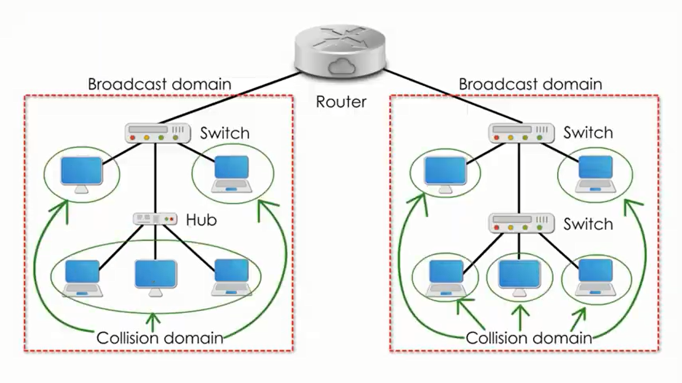
Collision domain is a portion of a network where collisions can occur if two devices attempt to transmit data at the same time. Broadcast domain is the set of all devices on a network segment that receive broadcast messages from each other.
In CSMA/CD, a node senses if the wire is busy. If another node happens to be transmitting at that moment, the node will wait a few milliseconds and rechecks the wire. If the wire is free, the node can send out its frame. The wire is essentially first-come-first-serve. When a collision is detected on the wire, all nodes stop transmitting and random “backoff” algorithms determine how long each node must wait in milliseconds before they can retransmit again. The node with the lowest random number will get to transmit first, but once the timers run out, all nodes have equal priority to retransmit.
Network Interface Card is a circuit board that is installed on a computer to connect to the network. Network adapter encompasses both hardware (NIC) and driver components responsible for network communication. Manufacturers assign a Media Access Control MAC address to a network adapter when it is produced, they are used for local addressing for traffic at the link level
Routing involves directing traffic between networks using routers and routing tables. A router is a network device that connects different networks together and directs data traffic between them. It operates at the Network Layer (Layer 3) of the OSI model and is responsible for making decisions about the best paths for data to travel from one network to another. Routers use logical addressing, such as IPv4 or IPv6, to identify devices and networks. Each interface of a router represents a different broadcast domain, preventing broadcasts from crossing between different subnets.
Routing tables are data structures stored in routers that contain information about known networks, the paths to reach them, and associated metrics. Routers use routing tables and dynamic routing protocols (such as Interior Gateway Protocol) to determine the best paths for data to travel between networks. The process involves periodic exchange of routing information, updating of routing tables, and selection of the most efficient routes based on various metrics.
Speed- 1-100Mbps wireless/ 1Gbps wired, Ports- 2/4/5/8, Transmission type- First broadcast, unicast and multicast
The OSI model is primarily the standardized network reference model. It describes how data and network information are communicated from an application on one computer through the network media to an application on another computer.

The OSI model abstractly describes the functionality provided in seven layers of protocols, dividing the communication complexity between systems/network in a layered architecture.
Layer 1 - The Physical layer is responsible for the transmission and reception of raw data bits (0s and 1s) over a physical medium.
- This can be electrical signals, optical signals (utilizing optical fiber or laser) or electromagnetic waves (in wireless networks).
- Before transmission, the digital bits are often encoded into electrical or optical signals and the characteristics of the physical signal are modified to carry data. For example, varying the amplitude or frequency.
- It includes the transmission medium, such as copper cables or fiber optics or wireless. It also dictates the transmission speed, the max bit rate and bandwidth.
- It specifies the physical arrangement of devices in a network (topology) and the transmission modes.
- Protocols used - Bluetooth, ethernet, WiFi
Layer 2 - The Data Link layer is responsible for reliable point-to-point and point-to-multipoint communication over a physical link.
- It begins by encapsualting the network datagram into a frame. This frame includes address info, flow control and error checks.
- each NIC is assigned a unique MAC address by the manufacturer, data link layer uses that MAC addressing to identify the source and destination.
- The Logical Link Control sublayer ensures proper sequencing and flow control of frames during data transmission.
- It includes error-detection mechanism such as Frame Check Sequence (FCS) to verify intergrity of received frames and uses CSMA/CD protocol to determine how devices coexist and share the available bandwidth in the transmission medium.
- In case of error, that specific frame is either discarded or requested again for retransmission.
- Protocols used - ARP
Layer 3 - The Network layer is responsible for routing and forwarding data between different networks, enabling communication across interconnected networks. It determines the best path for data across interconnected networks, using logical addressing, routing tables, encapsulation, and translation between logical and physical addresses.
- Each packet is assigned a logical network address, typically IPv4 or IPv6.
- It determines an optimal path for packet based on destination IP and router's routing table.
- The routing table are dynamically updated using routing protocols like Interior Gateway Protocols (RIP, OSPF) and Exterior Gateway Protocol (BGP).
- At each router along the path, the packet undergoes encapsulation and decapsulation. The router encapsulates the packet in a new frame suitable for the next network segment, adding a new header. At the destination, the final router decapsulates the packet to extract the original data.
- Protocols used - IPv4, IPv6
Layer 4 - The Transport Layer is responsible for ensuring reliable end-to-end communication between two devices across a network. It manages various aspects of data transmission, including error detection, flow control, and segmentation.
- The connection is established based on Transmission Control Protocol OR User Datagram Protocol.
- The data is divided into smaller units called segments, this is to fit in with the maximum size allowed for transmission over that network.
- Each segment is assigned a sequence number. Sequence numbers help in proper ordering and reassembly of segments at the destination, especially if it arrives in random order.
- Techniques like sliding window protocols are used to manage the rate of data transmission, preventing congestion and ensuring efficient data transfer.
- Errors are detected with cheksum info, If detected, retransmission will be requested for that corrupted segment.
- Protocols used - TCP, UDP
Layer 5 - The Session Layer is responsible for establishing, maintaining, and terminating communication sessions between two devices. A communication session is a logical connection between applications that enables them to exchange data.
- The session establishment begins with negotiating session parameters, such as the type of session (half-duplex or full-duplex), synchronization points to coordinate the flow of data, token-passing mechnism to control which device has permission to transmit data at given time and security features such as encryption and authentication, to ensure the confidentiality and integrity of data exchanged during a session.
- Protocols used - NFS, SQL
Layer 6 - The Presentation layer is responsible for ensuring that data is presented in formats that network entities understand. It deals with the translation, compression, and encryption of data to facilitate the exchange of information between different systems. The text identifies several file formats that it associates with this layer such as JPEG, MPEG, MIDI.
Layer 7 - The Application Layer is concerned with all the network services and functions. At this level, the data input and output takes place. The applications themselves are not in the layer such as Bittorrent, bitcoin.