Video demo:
The command station is based on ESP32 chip. Development is done with Arduino core for ESP32 on PlatformIO.
Planned features are:
-
✓ Running locos on main track via DCC
-
✓ Ops mode programming via DCC (reading CVs works)
-
Loconet interface with routing from several sources:
-
✓ Physical LocoNet bus
-
✓ LbServer (LocoNet over TCP) over WiFi
-
✓ USB-Serial interface (not tested)
-
-
✓ WiFi control via WiThrottle protocol (EngineDriver or WiThrottle)
-
❏ Stored turnout roster (partially done)
-
❏
DCC++ interface via USB-Serial or WiFi(No need at the moment)+
The intended primary interface of the command station is LocoNet. LocoNet messages are received and transmitted from physical LocoNet bus, WiFi, USB. However, if needed, LocoNet can be cut from project and DCC packet generation with corresponding API can be used to implement other interfaces, like DCC++. WiThrottle protocol is used to connect WiFi throttle to Command station and does not depend on LocoNet routing.
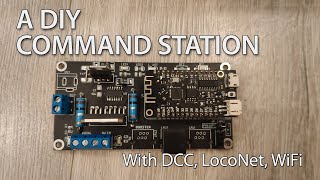
The current iteration of project is designed to work on a custom-designed PCB with Lolin32 Lite ESP32 module (that’s one of the cheapest ESP32 board). The board has L298N chip for DCC generation for both main and program tracks.
LocoNet part uses LM393 comparator with resistors adapted for 3.3V VCC levels. This circuitry is common in DIY LocoNet projects[1][2].
The PCB is open-source and is available here: https://oshwlab.com/positron96/loconet-command-station.
The project will also work on a breadboard with a L298N board (a red one with current sensing pins) and DIP versions of components. Other available LocoNet breakout boards will also work. They must operate at 3.3V. 5V levels on ESP32 GPIOs are out of spec (though it’ll probably work).
These pins are used on ESP32 for the following purposes:
-
LocoNet
-
RX - 16 (IN)
-
TX - 17 (OUT)
-
-
DCC Main
-
Data - 25 (OUT)
-
Enable - 32 (OUT)
-
Sense - 36 (analog in only)
-
-
DCC Prog
-
Data - 26 (OUT)
-
Enable - 33 (OUT)
-
Sense - 39 (analog in only)
-
-
Auxiliary:
-
Mode LED - 22 (OUT)
-
Mode button - 13 (IN)
-
User button - 15 (IN)
-
Pins are used as generic GPIO in/out/analog mode, so can be changed freely.
-
lib/DCC/DCC.h/.cpp: DCC packet generation library.
-
IDCCChannel- an interface for working with one track (main/programming). -
DCCESP32Channel- implementation of IDCCChannel. Contains structures to store packets, switch between allocated slots. A lot of architecture is derived from DCC++. -
DCCESP32SignalGenerator- a class that runs timer for DCC waveform generation. Contains references for 2 instances of IDCCChannel, so for both tracks only one timer is used.
-
-
CommandStation.h/.cpp: an API for a command station. The class finds, allocates, releases locomotive slots, sends programming data on programming tracks, stores turnout list. Calls functions from DCC.h to generate DCC packets.
-
LocoNetSlotManager.h/.cpp: a class that parses and generates LocoNet messages concerning command station functions. Does slot managing and programming. Calls functions from CommandStation.h for actual access to locomotives and tracks.
-
WiThrottle.h/.cpp: class for WiFi-based throttles (EngineDriver, WiThrottle and such). Calls functions from CommandStation.h for actual access to locomotives and tracks.
-
LbServer.h: LocoNet over TCP protocol implementation (for PC to connect wirelessly over WiFi). Parses data from TCP, injects LocoNet packets into LocoNet bus, sends back result of sending packet over physical bus. Packets from the bus are sent to TCP.
-
LocoNetSerial: an implementation of LocoNet over UART (for connecting to PC with USB cable). Since the connection does not allow controlling of RTS/DTR lines, usefulness of this function is limited. Not used at the moment, as serial port is used for debugging output.
Since this project is an Ultimate Command Station, it must accepts Loconet messages from different sources: physical LocoNet bus, USB-Serial, LbServer (LocoNet over TCP). All messages must be transparently routed to between all connected buses. It means that:
-
There must be a routing mechanism for broadcasting messages from one source to others.
-
Existing frontend classes (e.g. Throttle) must be separated from hardware backend and conncted to other sources. When command station itself generates a message (e.g. a reply to throttle), it must be broadcasted to all handlers.
-
Result of sending a message to the bus is only taken into account for real LocoNet bus; it is assumed that USB and WiFi always send packets successfully.
With this in mind, the LocoNet2 library was heavily redesigned and refactored. The LocoNet class is now separated into hardware backend (LocoNetPhy), a message parser (LocoNetDispatcher), and a routing bus (LocoNetBus) between them. Other sources of messages extend LocoNetConsumer class and are connected to the bus. and messages. Frontend classes (Throttle, FastClock, SystemVariable etc) are connected to the message parser instead of hardware class and so can handle messages from all sources.
The implementation is based on these libraries:
-
LocoNet2 - LocoNet bus support. The library is heavily modified to support several sources of loconet messages and to better use timers and RTOS tasks.
-
DCC library is based on DCCpp library and DCC++ project (heavily modified). Used for DCC packet generation.
-
WifiThrottle WiThrottle protocol. Mostly rewritten from scratch with the help of JMRI sources.
-
Embedded Template Library for statically-sized maps, vectors, bitsets etc.
Beware that CV reading/writing may not work for your decoder.
It appears that ADC on my esp32 changed its parameters over the year. It now does not detect decoder responses when reading/writing CVs. I tested with one particular decoder, the voltage over the shunt resistor is around 30mV, the resistor is 0.1 Ohm, so the current is 0.3A, which is within NMRA specs for basic acknowledge. However, the ESP32 shows non-zero readings only starting from around 80 mV, and ADC readings are around 2-8. This is actually within specs of ESP32 that state that measurable readings start from 100 mV. Somehow it did work much better before, as I have the ADC threshold in the code at 500 before. I had to lower it to 2, so now the CV reading somewhat works, but not reliably.
In the future version, a proper amplifier needs to be adde to the schematic. I am looking at this TI INA180.